
Home Lab, v1
30 Oct 2017In most part inspired by a certain Dr. White, I have been trying to put together a nominal hobby electronics lab over the last few months. This post is a reflection on the lab setup and some initial experiments.
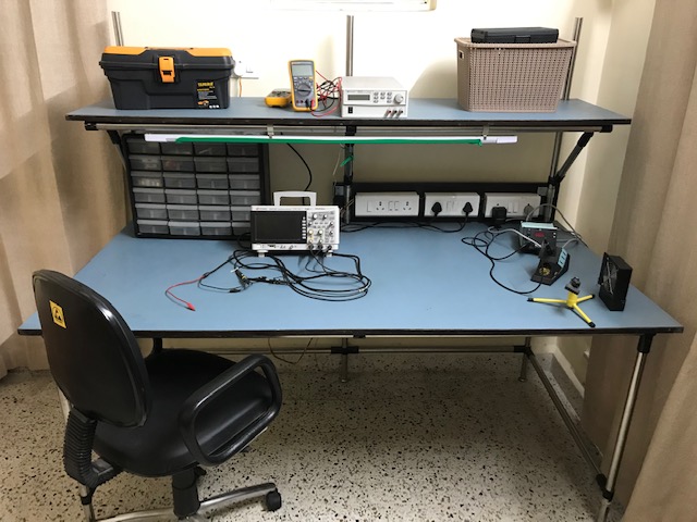
Here’s the setup.
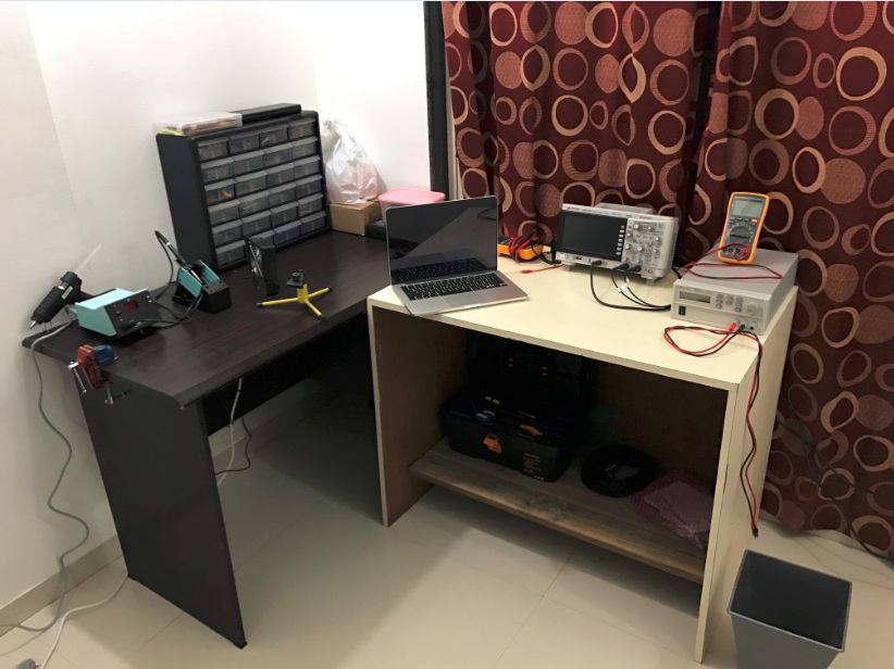
Here are the ingredients.
- Keysight DSOX1102G oscilloscope: A 70MHz bandwidth, dual channel oscilloscope with an integrated function generator. The only other oscilloscope I was considering was the Rigol 1054Z, but the built-in function generator (and also the Keysight/Agilent brand name) made me choose DSOX1102G.
- Fluke 17B+ DMM: A general purpose multimeter (2 qty). This is a neat multimeter with most features required for bench testing, but does not have a communication interface and is not a True RMS meter. Other alternative considered was Keysight U1230 series, which has both features mentioned before, but does not have sleep current measurement in the uA range.
- U8001 DC power supply: A rugged 0-30V, 0-3A power supply. This power supply is a continuation of the HP E3610 series, which has some good reviews. Cheap power supplies tend to misbehave as the AC input supply voltage fluctuates; had seen this happen before which made me stick with a proven power supply.
- Weller ESD81i soldering station: A 95W digital interface soldering station. I had heard good reviews of Haxo FX888D and i-CON Nano as well.
- Akro-Mils component cabinet: Rather surprisingly, I found it difficult to find a suitable component cabinet, but this one’s just fine.
These were the relatively expensive purchases, or purchases where some thought was put, before choosing the make. Apart from these, a special mention can probably go to a toolbox, such as this, for storing tools and accessories such as pliers, screw-drivers and the likes.
Before continuing with the rest of the blog post, a special mention of YouTube stalwarts, Dave Jones (who runs the EEVblog channel) and Alan Wolke (who runs the W2AEW channel) is due. Information sources such as these were super useful during the lab build up. Big thumbs up.
Okay, here are two of the early experiments.
Building a Colpitts oscillator
This blog post on Hackaday introduced me to the Manhattan style of prototyping, and it seemed worth a try. I had also wanted to build an oscillator circuit from building-block components for a long time. It turned out that the W2AEW had built a Colpitts oscillator using Manhattan prototyping method on his YouTube channel. Here’s the link to his video. My poor replica of the circuit build is shown below; except that I used islands from copper-clad PCB pieces, instead of drilling out islands as shown in the video.
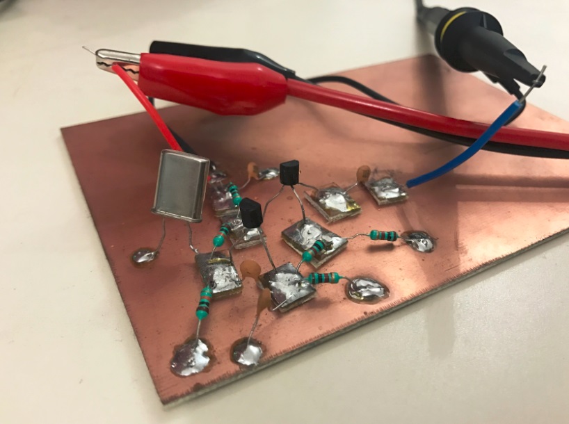
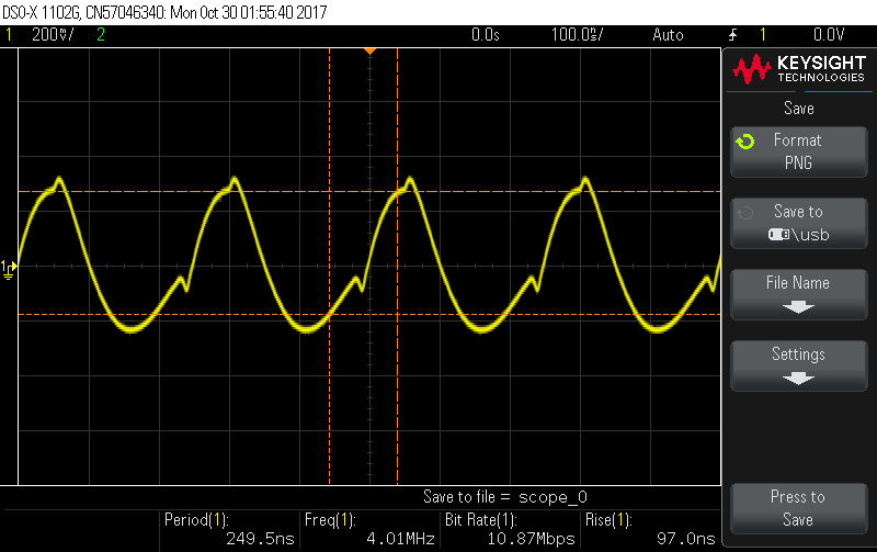
.. and the resulting wannabe sinusoid ..
Onto the next experiment ..
Measuring speed of light in a coax cable
I had come across this awesome video by Tektronix, on transmission lines. A video on the similar subject matter was here on W2AEW’s channel. These videos essentially showed how to measure the speed of transmission of electronic signals. I was blown away that such complicated experiments could be conducted with rather accessible instruments. In spirit of replicating the wheel, here are some notes from the replication.
The experiment is on sending short rectangular pulses over a coax cable, using a function generator (which in this case was part of DSOX1102G), and then measuring the time lag between the reflected wave and the transmitted wave to interpret the speed of travel of pulses. I used a 10 meter long coax cable with BNC terminals. One end of the BNC cable was connected to the function generator output (which was configured to generate pulse train with ON time of 20ns). The other end of the coax cable was connected to a terminating resistor (potentiometer).
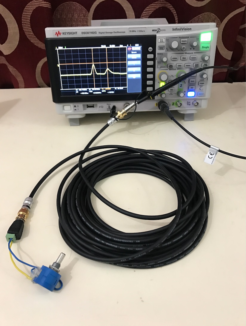
Depending on the value of terminating resistor, the amplitude and phase of reflected wave changes (impedance matching). When the far end of the coax cable is left “open” (ie, infinte resistance), the signal is reflected with maximum amplitude and with the same phase. When the far end of coax cable is “shorted” (ie, zero resistance), the signal is reflected, again with maximum amplitude, but with opposite phase. As we go from shorted to open, at a certain sweet spot, we observe no reflection.
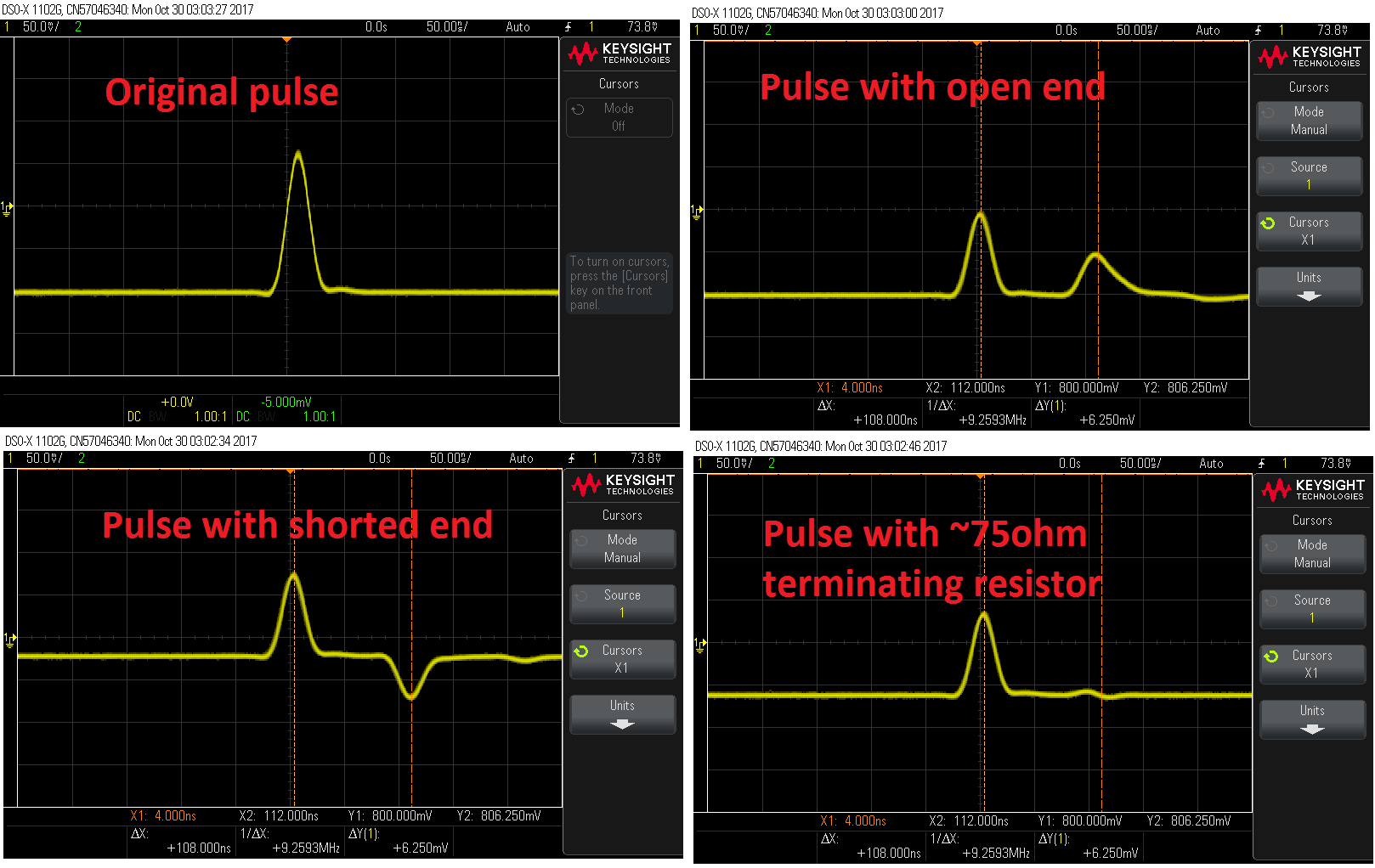
The “sweet spot” happened at a resistor value of around 75 ohm, which is one of the two standard impedances for coax cables (the other being 50 ohm). This adds to the confidence on the legitimacy of the experiment.
When the termination is either open or short, measuring the time lag between transmitted and received signals can give a fair idea of speed of transmission of the pulse in the coax medium. The time lag was measured to be around \(105 ns\), and with a total travel distance of \(20m\) (to-and-fro), the speed of signal gets computed as \(20/105 \times 10^9 m/s = ~1.9 \times 10^8 m/s\). The velocity factor of coax medium is 2/3; ie, expected speed of light in coax medium is 2/3 of speed of light in vacuum. The expected value of speed of light in coax is \(2 \times 10^8 m/s\), which is tantalizingly close to the measured value. Awesome!
On a concluding note, building a minimal home lab is fairly straight forward and can be wrapped up in weekends worth couple of months. To be honest, I have not spent significant time on the lab since setting it up, but even the nominal experiments performed so far have been very satisfying. Do reach out if you want to set up a lab, and I can try to help around!
Update: The lab went through a makeover sometime in early 2018.
comments powered by Disqus