
Notes on Opamp Bandwidth
20 Mar 2015Opamp datasheets usually provide certain parameters to specify the frequency response of the opamp. An often misunderstood spec is on the Gain Bandwidth Product. I have traditionally had a poor understanding of this subject matter; hope this post helps clear things up for those in similar shoes.
The transfer function of a typical opamp has a real dominant pole at a fairly low frequency (a few Hertz). The opamp’s transfer function can be approximated by:
\(A_0\) is the DC gain and \(\omega_0\) is the dominant pole frequency (which is also referred as the \(-3dB\) bandwidth of the opamp). The gain of the opamp at frequency \(\omega\) can then be calculated as:
Gain Bandwidth Product is usually defined for dominant pole compensated opamps. For frequencies beyond \(-3dB\) frequency (\(\omega_0\)), the product of gain and frequency is constant. Unity Gain Bandwidth and Gain Bandwidth Product have the same value for a dominant pole compensated opamp. ie, \(GBWP = A_0 \omega_0\). Shown below is the Bode plot of the frequency response of the opamp discussed above.
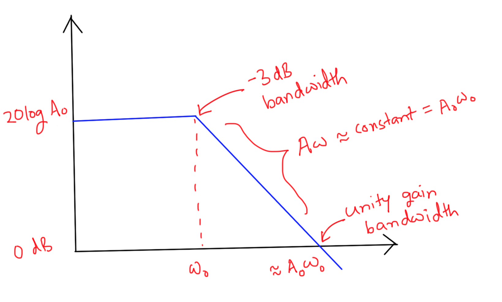
If we were to plot the Gain vs Frequency graph on a linear scale (instead of the log-log scale as in the Bode Plot), the curve would approximate a hyperbola (a bit beyond \(\omega_0\)).
GBWP of non-inverting amplifier
There is yet another way to interpret the GBWP of opamps. Here is the classic non-inverting amplifier configuration.
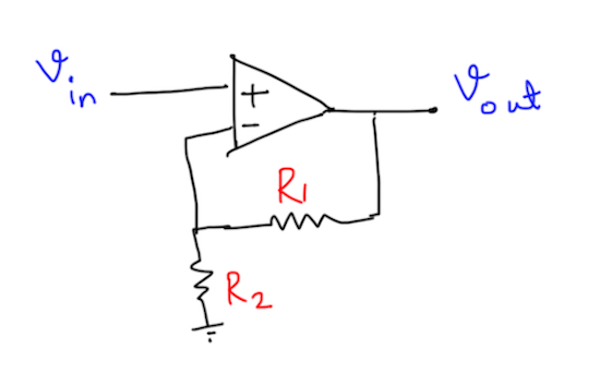
We usually come across statements which say that the \(-3dB\) bandwidth of this amplifier is GBWP divided by Gain. However, this statement is not quite obvious. Let us formally prove that this is indeed the case. At a block diagram level, this circuit can be equivalently represented as follows:
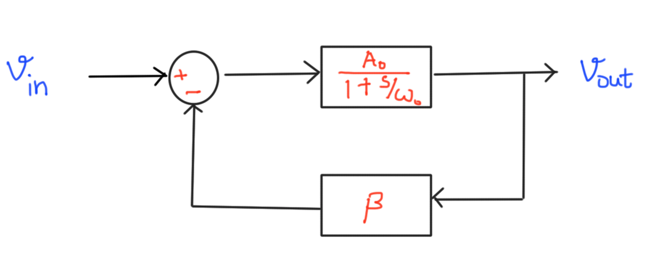
where \(\beta = \frac{R_2}{R_1 + R_2}\). The closed loop transfer function of this new system is
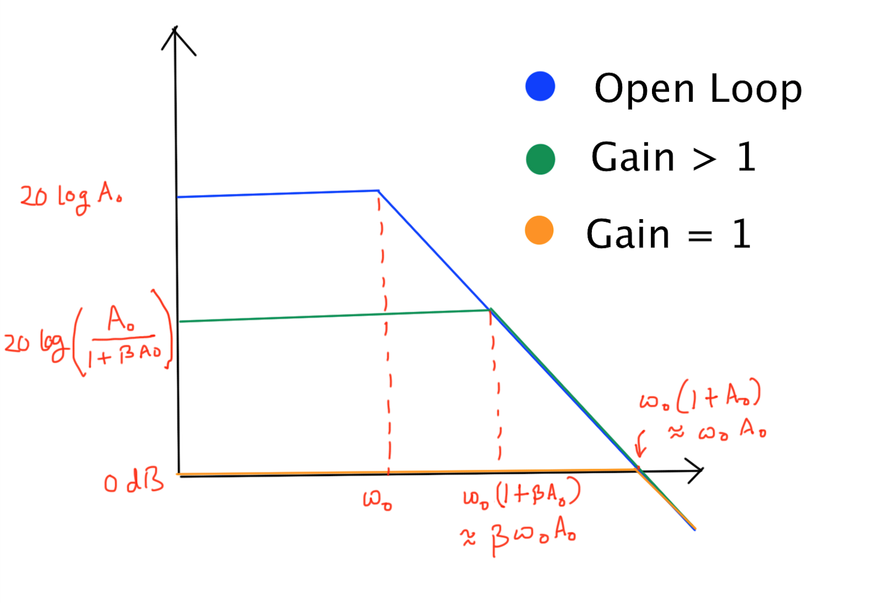
Observe that \(A_0 \omega_0 = A_1 \omega_1\). The graph below shows the effect of the \(\beta\) on the Gain Bode Plot of the amplifier.
Bandwidth of Cascaded Opamps
Consider \(n\) identical cascaded opamps, where each of the opamp has a resistive feedback loop with a certain \(\beta\). If the GBWP of the opamp is known, then can we somehow predict the GBWP of the cascaded system?
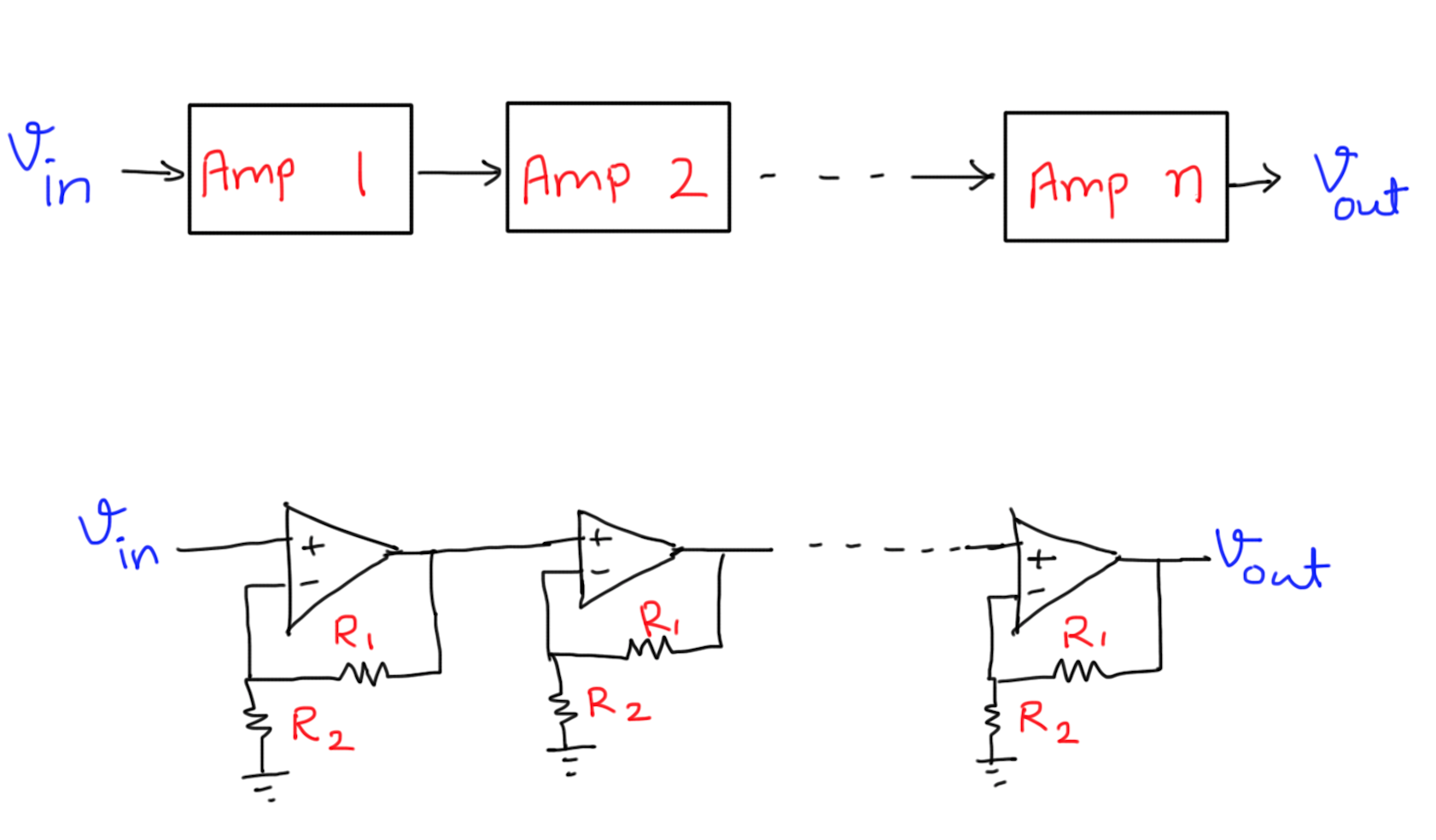
Each of the amplifier has a GBWP as \(A_0 \omega_0\), and since the gain of each amplifier stage is determined by \(R_1\) and \(R_2\), (gain = \(K = A_0 \frac{R_1 + R_2}{R2}\)) => the bandwidth of each amplifier stage is \(\omega_0 \frac{R_2}{R_1 + R_2}\). On first look, it appears that the bandwidth of the cascaded system should also be \(\omega_0 \frac{R_2}{R_1 + R_2}\), but that is not exactly the case. The straight line approximation in bode plot is not good enough in this case! Let us find out the true \(-3dB\) bandwidth.
Say we have a specific opamp with a \(1 MHz\) GBWP. If we were to use this opamp to get a gain of \(1000\), the \(-3dB\) bandwidth would drop to around \(1 kHz\). Instead, if we use \(3\) cascaded opamps (each with a gain of \(10\), and hence, an individual bandwidth of \(100 kHz\)), the cumulative bandwidth of the cascaded system would be
That’s it for today!
Tweetcomments powered by Disqus